What Are CNC Milling Parts and How Are They Made?
Cnc Milling Parts sit at the center of modern precision manufacturing. They appear in robotics, medical devices, aircraft systems, and industrial machinery. A milling machine removes material from a solid block, creating accurate shapes through programmed tool movement. The process can produce flat faces, deep pockets, narrow slots, curved surfaces, and complex three-dimensional features.
Professor Yusuf Altintas, a respected authority in machining science, has said, “Machining is the controlled removal of material.” That principle explains the process clearly. A digital CAD model guides the CAM program. The CNC controller then directs the spindle, cutting tool, and worktable. Operators still matter. They select suitable tooling, set cutting speeds, inspect dimensions, and correct problems before production continues.
Small details decide quality. A dull end mill can leave visible tool marks. Excessive cutting speed may burn the workpiece. Poor clamping can shift a part by a fraction of a millimeter. That error can affect an entire assembly. Materials also behave differently. Aluminum cuts quickly, while stainless steel demands careful heat and chip control.
This article examines what Cnc Milling Parts are and how manufacturers make them. It follows the journey from drawing to finished component. Some choices remain less obvious. The cheapest method is not always the most reliable. Even experienced teams must test, measure, and rethink their assumptions. That practical discipline creates parts that fit, perform, and remain dependable in real applications.
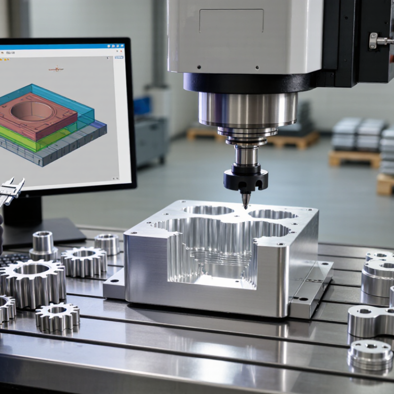
What CNC Milling Parts Are and What They Do
CNC milling parts are components shaped by rotating cutters controlled through computer instructions. They may become brackets, housings, gears, fixtures, or medical-device frames. Their job is practical: hold loads, guide movement, protect internal systems, or connect larger assemblies. A milled part is not merely a block with holes. Each surface can control alignment, sealing, heat transfer, or motion.
The process begins with a digital drawing and suitable material. Aluminum supports lightweight structures, while steel offers greater strength and wear resistance. The machine removes material through facing, slotting, drilling, pocketing, and contouring. Cutting speed, feed rate, tool geometry, and coolant affect the final result. Grand View Research estimated the global CNC machine market at about USD 83.8 billion in 2023, showing the scale of digital machining demand. The International Federation of Robotics reported 4.28 million industrial robots operating worldwide in 2023. That figure reflects wider factory automation, where CNC-milled parts often serve as precise interfaces.
Accuracy depends on more than machine capability. It depends on drawings, fixturing, tool wear, inspection, and operator decisions. The weak point may be an unclear tolerance. A perfect machine cannot repair poor specifications. In practical production, coordinate measuring machines can verify critical dimensions, while visual checks catch burrs and surface damage. Some parts still need refinement after testing. That is not failure. It is evidence that real loads can reveal assumptions hidden in a drawing.
Key Materials Used in CNC Milling Parts
What Are CNC Milling Parts and How Are They Made?
Key Materials Used in CNC Milling Parts
CNC milling parts begin as solid blocks, bars, or plates. A programmed cutter removes material along several axes. Material choice controls weight, strength, heat resistance, surface finish, and machining cost.
Aluminum is widely used for housings, brackets, and aerospace structures. The U.S. Geological Survey reported about 70 million metric tons of primary aluminum production worldwide in 2023. It machines quickly and resists corrosion, but thin aluminum walls can vibrate or deform.
Steel provides higher strength for shafts, fixtures, and load-bearing components. Stainless steel offers corrosion resistance, although it generates more heat during cutting. The International Stainless Steel Forum reported global stainless-steel production of approximately 58.4 million metric tons in 2023.
Brass cuts cleanly and suits fittings, electrical parts, and decorative components. Titanium is strong and lightweight, but poor heat transfer makes it demanding to machine. Engineering plastics reduce weight and electrical conductivity, yet they may creep under continuous loads.
Tips: Match the material to the service environment, not just the drawing. Confirm hardness, heat treatment, and material certification before machining. Test thin sections carefully. A perfect toolpath cannot fix unsuitable material selection. In practice, machinists sometimes choose a less expensive alloy, then discover that finishing or distortion increases the real cost. That mistake deserves review.
How a CNC Milling Machine Shapes Each Part
A CNC milling machine shapes each part by guiding rotating cutters across a secured block of material. The process begins with a digital model and a carefully planned cutting path. An operator checks the drawing, material grade, and required tolerances before production starts. The raw stock is clamped firmly on the machine table. Workholding must be rigid. A loose setup can create vibration, poor surfaces, or inaccurate dimensions.
The machine removes material in controlled passes. Roughing cutters clear large amounts quickly, while smaller tools create slots, pockets, holes, and angled faces. Finishing passes move more gently across the surface. Small changes matter. Cutting speed, feed rate, and tool condition all influence the final result. During cutting, coolant may carry chips away and reduce heat near the tool. The operator watches the sound, surface texture, and chip shape. A high-pitched sound may indicate vibration or a worn cutter.
After machining, the part is measured with calibrated instruments. Critical dimensions are compared with the approved drawing. Edges are deburred, and the surface is inspected under clear lighting. Still, mistakes happen. A tool may wear earlier than expected, or a clamp may shift slightly. Reviewing these issues improves later setups and makes the process more reliable. CNC milling is precise, but it still depends on thoughtful preparation and honest inspection.
Essential Stages of CNC Milling Part Production
CNC Milling Parts: Essential Stages of Production
Producing a CNC milling part begins with a controlled design review. Engineers check dimensions, tolerances, material behavior, and tool access before programming. A digital model is converted into cutting paths, then reviewed for collisions and unnecessary movements. This stage often reveals a sharp internal corner or an unrealistic tolerance. Small changes here can prevent expensive rework later.
Material is cut from a secured workpiece after the machine is set up. The operator aligns the stock, installs suitable cutters, and verifies the work coordinate system. A dry run or simulated cycle helps confirm the sequence. Machining usually moves from roughing to semi-finishing and then finishing. Coolant may control heat and remove chips. Measurements are taken during production, not only at the end. Calipers, micrometers, or coordinate measuring equipment can check critical features. The first piece may need adjustment. It is not always perfect.
Tips: Keep drawings clear and tolerances realistic. Match cutter diameter to feature size. Clean the fixture before every setup. Record tool wear and inspection results. These simple records improve repeatability, although they cannot replace skilled judgment. After machining, parts may receive deburring, surface treatment, or cleaning. Final inspection compares actual dimensions with the approved drawing and confirms that edges, holes, and surfaces meet the required condition.
Quality Checks for Finished CNC Milling Parts
CNC milling parts are shaped by rotating cutters that remove material from metal, plastic, or composites. Quality checks confirm that the final component matches its drawing, not merely its appearance. The ISO Survey 2022 recorded 1,265,216 ISO 9001 certificates worldwide, showing how widely documented quality systems support manufacturing control.
Inspectors begin with traceable material certificates and calibrated measuring tools. A coordinate measuring machine checks critical dimensions, hole locations, and flatness. Micrometers verify shaft diameters, while thread gauges test internal and external threads. Surface roughness testing can identify cutter wear that visual inspection misses. For example, a drawing may require Ra 1.6 μm, but an acceptable-looking wall can measure higher. First-article inspection compares the first completed part against every key feature. In-process checks then catch tool drift before an entire batch is affected. Inspection plans are useful, but they are not flawless. Human judgment still matters.
Tips: Mark each inspected feature directly on the drawing. Record actual measurements, not only pass or fail results. Check burrs around holes with a fingertip and proper lighting. Store calibrated instruments away from coolant and vibration. Review rejected parts for patterns, because repeated small errors often reveal tool wear, fixture movement, or unclear instructions. A 2023 smart manufacturing survey reported that 86% of manufacturers viewed smart production as a major competitive priority. That ambition requires reliable measurement data, not attractive dashboards alone.
What Are CNC Milling Parts and How Are They Made?
Quality Checks for Finished CNC Milling Parts
This chart shows realistic example acceptance limits for a precision-milled aluminum component. Smaller values indicate tighter control requirements. Actual limits are defined by the engineering drawing, material, machine capability, and inspection method.
