
How to Choose the Right SBMA Connector for Your Needs?

Choosing an Sbma Connector is not just a matter of finding a part that fits. A connector may look compatible yet differ in interface, cable termination, or rated operating range. Those small differences can affect signal performance and installation reliability. Start with the equipment’s documentation, then confirm the connector series and mating interface against the manufacturer’s specifications. Looks can mislead.

Next, consider the conditions around the connection. Check the required frequency range, impedance, cable type, available space, and expected number of mating cycles. If the assembly will face vibration, moisture, or temperature changes, review the connector’s environmental ratings rather than relying on appearance. A compact body can help in a crowded enclosure, but it may be harder to install or inspect. That trade-off is easy to miss.

A careful selection process also checks practical details: termination method, mounting style, materials, and tool access. Compare the product datasheet with the cable and device requirements, and ask the supplier to clarify any unclear dimensions or compatibility claims. Avoid assuming that similar names mean interchangeable parts. Even experienced buyers can overlook one detail when replacing a connector in an existing system. This guide explains how to evaluate those factors, compare suitable options, and make a choice that fits both the electrical requirements and the real installation. There may not be one perfect connector; the right choice depends on the application and verified specifications.
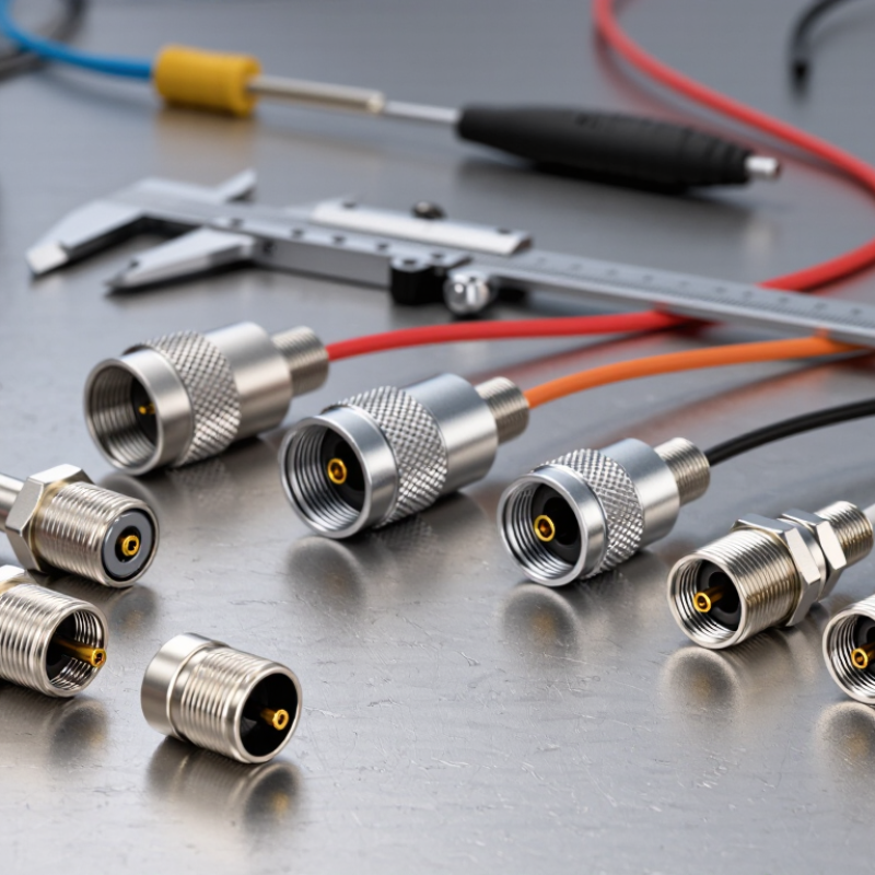
How to Choose the Right SBMA Connector for Your Needs?

What Is an SBMA Connector and Where Is It Used?

An SBMA connector is a compact, 50-ohm blind-mate coaxial interface. It joins RF modules when direct access is limited, such as inside a rack or behind a removable panel. Unlike a threaded connector, it can mate through a guided push-on connection, helping technicians replace modules without twisting a cable. The exact frequency range depends on connector design and installation; check the specified operating band, return loss, and mating-cycle rating rather than assuming all SBMA parts perform alike. Small details matter.

SBMA connectors are used in modular radio equipment, test systems, and other assemblies where space is tight and repeatable connections matter. The GSMA’s Mobile Economy 2024 report estimated 1.6 billion 5G connections worldwide at the end of 2023, with 5.5 billion projected by 2030. That growth signals expanding radio infrastructure, but it does not mean every 5G device needs an SBMA interface. This distinction is easy to miss. In practice, engineers should compare the connector’s frequency and power limits with the equipment specification, then verify alignment tolerance and cable routing in the actual chassis. A connector that fits on paper may still be awkward to service.

How to Choose the Right SBMA Connector for Your Needs?

SBMA connectors are blind-mate RF coaxial connectors used in compact modular assemblies, including communications equipment and test systems. Compare your operating bands with the connector’s specified frequency range, then check impedance, board layout, mating tolerance, and environmental requirements.

The bars show the upper edge of selected, commonly used RF bands—not connector performance ratings. Many SBMA designs are rated up to 18 GHz, but the usable range depends on the specific connector and assembly. Confirm the datasheet specifications for your application.

Define Your Frequency, Impedance, and Power Requirements

How to Choose the Right SBMA Connector for Your Needs?

Define your frequency, impedance, and power requirements before comparing connectors. Published BMA-family specifications commonly list 50-ohm impedance and operating ranges up to 18 GHz; some designs extend to 22 GHz. These are reference figures, not guarantees for every SBMA assembly. IEC 61169-33:2012 provides a standards-based reference for BMA connector interfaces and testing, but the exact SBMA specification still matters. Check the connector’s rated frequency, return loss, and insertion loss alongside the cable and mating interface. A connector rated for the band may still underperform in a poorly assembled cable.

Power ratings need context. A published wattage may assume a particular frequency, ambient temperature, and VSWR. Higher mismatch can increase reflected energy and heating, especially during continuous transmission. Compare average and peak power ratings, then apply the supplier’s derating curve for your operating conditions. If the system must work near its limits, verify performance with a calibrated vector network analyzer and a suitable power test. Small details matter.

Tips: Write down the frequency band, 50-ohm requirement, and worst-case power before ordering. Confirm whether the rating is continuous or peak. Ask for test data at your operating frequency. I once overlooked cable loss in a comparison; the connector was not the weak link. It is an easy mistake to make.

How to Choose the Right SBMA Connector for Your Needs? – Define Your Frequency, Impedance, and Power Requirements
Selection Dimension Example Requirement What to Specify or Check Selection Guidance
Operating frequency Example system band: 2–6 GHz State the full operating range, including the lowest and highest frequencies and any harmonics that must pass through the connection. Choose an SBMA assembly whose specified frequency range covers the entire system band. Confirm performance for the complete connector assembly, not just the interface.
Characteristic impedance 50 Ω RF system Confirm the connector, cable, PCB launch, and connected equipment use the same nominal impedance. 50 Ω is common in RF test and communications systems. Do not treat 50 Ω and 75 Ω interfaces as interchangeable; an impedance mismatch can increase reflections.
Continuous RF power Example system demand: 5 W continuous at the highest operating frequency Specify power at the connector, frequency, ambient temperature, duty cycle, and any relevant cooling conditions. Compare the requirement with the assembly’s power rating under matching conditions. Power handling generally decreases as frequency or temperature rises; there is no single rating that applies to every SBMA assembly.
Peak power and duty cycle Pulsed signal: 20 W peak, 10% duty cycle Provide peak power, pulse width, repetition rate, duty cycle, and waveform where applicable. Do not infer peak-power capability from an average-power rating. Check both peak voltage or power limits and average heating limits with the supplier’s technical data.
Return loss or VSWR Example target: VSWR ≤ 1.5:1 across the required band Set the acceptable mismatch across frequency and include the mated connector pair, cable, and PCB transition in the evaluation. A lower VSWR indicates a better impedance match. Verify the test conditions and whether the published result applies to a connector alone or to a complete assembly.
Blind-mate alignment Module installed without direct visual access to the connector Check allowable axial and radial misalignment, engagement depth, mounting tolerances, and the guidance features in the mechanical design. Confirm that the connector’s specified blind-mate tolerance accommodates the actual chassis and PCB tolerance stack-up. Avoid using the connector to compensate for excessive misalignment.
Mechanical life and vibration Frequently removable module in a vibration-exposed system Specify expected mating cycles, vibration and shock environment, retention needs, and service interval. Compare the documented durability and environmental qualification of the exact connector assembly with the application. Mating life and vibration performance are product-specific.
Cable, mounting, and environment Board-to-board connection in a compact enclosure Define cable type or PCB interface, available space, mounting method, temperature range, and exposure to moisture or contaminants. Check the exact assembly drawing, cable bend limits, mounting footprint, and environmental ratings. Connector families and configurations can differ in dimensions and sealing.

Example requirements are illustrative system inputs, not performance ratings for all SBMA connectors. Confirm electrical, mechanical, and environmental limits in the technical documentation for the exact connector assembly.

Match the Connector to Your Cable and Mounting Setup

How to Choose the Right SBMA Connector for Your Needs?
Match the Connector to Your Cable and Mounting Setup

Start with the cable, not the connector catalog. Check its outer diameter, conductor size, shielding, and bend radius. The rear cable clamp must grip the jacket without crushing it. A mismatch can loosen under vibration or strain the cable at the exit. Measure the cable you will actually install; nominal sizes can be misleading. Tight space? Check the connector’s full rear profile, including backshell and boot.

Then match the interface to the mounting point. Panel thickness, cutout size, available clearance, and access for tightening all matter. A bulkhead connector may suit a fixed panel, while a cable-mounted version may work better between moving assemblies. Leave room for the coupling nut and a gloved hand. It is easy to overlook that detail on a drawing. For harsh environments, verify the assembled system’s protection rating, not just the connector’s. IEC 60529 defines IP67 as dust-tight protection and resistance to temporary immersion up to one metre for 30 minutes. That rating only applies when the specified seals and installation conditions are maintained. Use IEC 60512 test methods to check electrical and mechanical performance against the application. A quick fit check with the real cable often catches problems before production.

Assess Environmental and Mechanical Conditions

Assess the environment where the SBMA connector will operate, not just the conditions inside the equipment. Outdoor or industrial installations may expose it to moisture, dust, salt spray, or wide temperature swings. Check the connector’s specified temperature range and sealing requirements against the actual enclosure design. A connector rated for a demanding environment can still fail if water reaches its mating interface. Small details matter.

Mechanical conditions deserve equal attention. Measure available clearance and estimate how much vibration, shock, and cable movement the connection will face. In a compact rack, slight misalignment during blind mating can place unwanted stress on the interface. Support nearby cables so their weight does not pull on the connector. For mobile equipment, review vibration and shock ratings, then consider whether mounting points need reinforcement. Also check the expected mating cycles; frequent service access changes the wear picture. A quick fit check is useful, but it cannot replace the manufacturer’s drawings and test data. There is rarely one perfect setup. Real installations are messier than a bench test, and that is worth remembering.

Check Compatibility, Standards, and Installation Needs

Before choosing an SBMA connector, compare its interface with the equipment drawing and cable assembly. Check the mating type, dimensions, impedance, and operating frequency. A connector that looks close may still fail to seat correctly or maintain the intended signal path. Fit matters. Confirm the cable diameter and termination method, too; these affect routing and strain on the connection.

Review the applicable standards listed for the equipment, cable, and connector. Do not assume that two parts are compatible because both meet a similar specification. Check the rated frequency, environmental limits, and any required test documentation.

For installation, follow the specified torque and use the recommended tool. Keep the connector aligned while mating, and leave enough clearance for the cable’s bend radius. Small details matter. A rushed installation can damage the interface or create an intermittent connection that is hard to diagnose later.

It is easy to overlook mounting space during selection, so check the actual panel or enclosure before ordering. An extra measurement is rarely wasted.

Article Source:

Go to Top